2026-09-24
Content
A maintenance technician walks along a 14-meter loading platform edge, clipping a lanyard to a steel cable overhead. The cable runs between two anchor points and passes through intermediate brackets. If the technician slips, the system must arrest the fall without dragging them into a lower hazard or overloading the structure. That outcome depends on a cable fall arrest system engineered around four variables: span, tension, clearance, and anchor capacity. Get those four right, and the system delivers mobility, fall protection, and predictable performance. Get them wrong, and the cable becomes a decorative wire with no reliable safety function.
A cable fall arrest system is a horizontal or vertical lifeline made from wire rope, secured by terminal anchors and intermediate supports. Workers connect to the cable with a guided type fall arrester, a lanyard, or a self-retracting device, depending on the configuration. Unlike a fixed guardrail, the system allows movement along a defined path while maintaining continuous attachment. The cable does not eliminate the fall; it arrests the fall within a calculated distance and limits the forces transmitted to the worker and the structure.
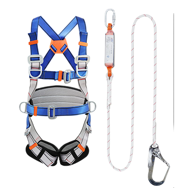
The main components are straightforward: end anchors, intermediate brackets, tensioners, shock absorbers, cable, and connecting hardware. Each part has a role. Anchors transfer load to the building structure. Intermediate brackets keep the cable aligned and prevent excessive sag. Tensioners set the initial preload. Shock absorbers reduce peak forces during a fall. Connectors link the worker's harness to the cable system. A single weak component can undermine the entire arrangement, which is why design and installation belong together.
Horizontal systems suit rooftops, catwalks, loading docks, and bridge inspection paths. Vertical systems serve ladders, silos, and tower climbs. Some projects combine both. The choice depends on travel direction, fall clearance, and the number of users. A cable system can support one user or several, but only when the design explicitly accounts for multi-user loading. Otherwise, two workers falling at once can exceed the anchor and cable capacity.
Span dictates almost everything. A longer unsupported span increases cable sag, raises the required tension, and amplifies the dynamic force when a fall occurs. Short spans with close intermediate brackets behave more predictably and need less clearance below. However, adding brackets costs money and may conflict with overhead equipment. The practical balance is a span that keeps sag within acceptable limits while preserving the worker's freedom of movement.
Tension is the second variable. Manufacturers publish a recommended installation tension range, often expressed in kilonewtons. Too little tension creates excessive sag and a harsh fall arrest. Too much tension preloads the anchors and can cause fatigue at terminations. Temperature changes the tension as well. Steel cable expands and contracts with heat and cold, so a system installed on a hot afternoon may lose tension on a freezing night. Periodic tension checks keep the system inside its design envelope.
Clearance is the third variable. The total fall distance includes free fall, deceleration distance, harness stretch, and a safety margin. If the calculated distance exceeds the space below the work surface, the worker can strike a lower level or the ground. A cable system with a long span and a soft arrest may need more clearance than a rigid rail. Designers calculate clearance before choosing hardware, not after.
Anchor capacity is the fourth variable. Every anchor must resist the maximum expected force with an appropriate safety factor. Concrete, steel, timber, and composite panels behave differently. A single anchor designed for a 10 kN load may fail if the actual fall generates 15 kN. Structural verification, pull testing, and documented load ratings are non-negotiable for permanent installations.
The chart compares relative installation cost for horizontal cable systems at different unsupported spans. A 10-meter span requires fewer intermediate brackets and lighter anchors, so the relative cost sits at 35. As the span grows to 50 meters, the system needs more brackets, stronger terminations, and often a larger cable diameter, pushing the relative cost to 100. The relationship is not perfectly linear because anchor conditions and roof type add their own costs. Still, the trend shows that span reduction is one of the most effective ways to control project budget. Designers should treat the chart as a planning tool, not a quotation, and verify actual pricing with a qualified supplier.
Cable fall arrest systems fall under several standards depending on the region and application. OSHA 1910.140 and 1926.502 address general industry and construction requirements in the United States. ANSI Z359.6 provides design criteria for active fall protection systems. EN 795 covers anchor devices, while EN 353-1 and EN 353-2 address guided type fall arresters on vertical and horizontal lifelines. These documents do not all say the same thing, so a system designed for one market may need modification for another.
Compliance is not a paper exercise. It requires calculations, drawings, load ratings, and installation records. A stamped design from a qualified engineer gives the project a defensible baseline. After installation, a competent person should verify tension, alignment, anchor condition, and clearance. The verification should be documented and repeated at intervals defined by the manufacturer or the local authority. Without records, a system may pass a visual glance but fail a formal audit.
Testing also matters for hardware. Carabiners, fall arresters, and shock absorbers should carry recognized certification marks and traceable batch numbers. Counterfeit or uncertified components are a persistent risk in safety supply chains. Buyers should request test reports and confirm that the product matches the certificate. This step is simple, but it prevents the most common failure mode: a system assembled from parts that were never designed to work together.
Cable is not the only answer. Rigid rail systems offer smoother trolley movement and less sag, but they cost more and require precise alignment. Guardrails provide collective protection without user training, yet they obstruct movement and may not suit irregular roof geometry. Personal fall limiters work well for short-range tasks but do not support horizontal travel. The right choice depends on task frequency, number of users, structural capacity, and maintenance resources.
The radar chart compares a cable fall arrest system with a rigid rail system across six practical dimensions. The red polygon represents cable, while the dark grey polygon represents rigid rail. Cable scores well on span flexibility and low cost because it can follow curves and long distances with moderate material expense. Rigid rail scores higher on low maintenance and multi-user capacity due to its fixed track and predictable trolley movement. Cable tends to require more clearance because it sags and stretches under load. Corrosion resistance depends on material selection, so both systems can improve with stainless steel or galvanized components. The comparison is not a verdict; it is a prompt to match the system to the task rather than defaulting to one technology.
Cable systems appear wherever workers need to move horizontally at height while remaining attached. Rooftop maintenance, loading platforms, catwalks, bridge inspection, stadium rigging, and utility towers are common examples. Industrial plants use them over tanks, conveyors, and process equipment. Data centers use them above server rows. Shipyards and barge terminals use them along deck edges. The common thread is a defined travel path with limited turning radius and a structure capable of supporting anchor loads.
Environmental conditions shape material selection. Coastal sites and chemical plants need stainless steel cable or galvanized components. Cold storage and freezer rooms require tension settings that account for low-temperature contraction. High-temperature areas may need heat-resistant fittings. A single cable specification cannot serve every site, so buyers should share the operating environment with the designer before fabrication.
The line chart shows how cable tension changes as temperature rises from minus 20 to 30 degrees Celsius. At minus 20 degrees, the cable is contracted and tension sits near 4.0 kilonewtons in this example. As the temperature climbs, the steel expands and tension increases gradually. By 30 degrees, the tension reaches approximately 6.8 kilonewtons. This shift matters because the installation tension set on a cold morning may become too high on a hot afternoon. Conversely, a system tensioned on a hot day may become slack in winter. The chart supports a simple practice: record the temperature during tensioning and provide a seasonal adjustment range in the maintenance plan.
Buying a cable fall arrest system is a project, not a parts order. The checklist below covers the decisions that most often cause rework, delays, or unsafe installations. Use it during pre-design meetings and again before finalizing the purchase order.
| Consideration | Why It Matters | Verification Point |
|---|---|---|
| Span and bracket spacing | Controls sag, tension, and fall clearance | Engineering drawing with maximum span noted |
| Anchor capacity | Prevents structural failure during arrest | Pull test report or structural calculation |
| Number of users | Affects cable size, anchors, and shock absorber | Written user limit and training record |
| Clearance distance | Avoids lower-level impact after a fall | Fall clearance calculation for worst case |
| Corrosion environment | Determines cable and fitting material | Material certificate and coating specification |
| Inspection access | Keeps the system compliant over time | Maintenance plan with interval and records |
Impact force is not a fixed number. It depends on fall distance, worker weight, lanyard type, and the energy absorber. A cable system with a shock absorber spreads the arrest over a longer distance, which lowers the peak force. A rigid connection without absorption produces a sharp spike that can injure the worker and damage the structure. The chart below shows a simplified relationship for a 100 kg worker using a personal energy absorber on a cable system.
The 3D bar chart plots free fall distance against peak impact force for a simplified cable arrest scenario. At 0.5 meters of free fall, the peak force is about 4.0 kilonewtons. As free fall increases to 2.5 meters, the peak force rises to roughly 10.0 kilonewtons. The upward trend is steep because kinetic energy grows with the square of velocity. An energy absorber reduces the peak by extending the deceleration distance, but it cannot eliminate the effect of free fall entirely. Designers should minimize free fall through anchor placement and lanyard length before relying on absorption. The chart is illustrative and not a substitute for manufacturer data or a site-specific calculation.
A cable system is only as good as its maintenance. Inspections should check cable condition, corrosion, broken wires, tension, anchor tightness, bracket alignment, and hardware wear. The manufacturer usually defines a pre-use check, a periodic inspection, and an annual comprehensive inspection. Records should include date, inspector, findings, and corrective action. If a fall occurs, the system and the connected equipment must be removed from service until a competent person approves reuse.
Training is equally important. Workers need to know how to connect, how to move past intermediate brackets, how to avoid creating a slack lanyard, and how to respond to a fall. Rescue planning belongs in the same conversation. A worker suspended in a harness can develop suspension trauma within minutes, so the site must have a rescue method that does not rely on the fallen worker to self-rescue. Drills turn a written plan into a workable response.
For permanent installations, a maintenance contract with a qualified provider reduces the risk of missed inspections. The provider can also verify that replacement parts match the original design. Mixing components from different systems is a common mistake, especially when a bracket or cable is replaced after damage. The replacement may fit physically but fail the load rating. Documentation and part traceability prevent that error.
Start with a hazard assessment that identifies every edge, opening, and travel path at height. Then calculate clearance, span, tension, and anchor loads before selecting hardware. Choose materials for the operating environment, not just the lowest price. Confirm that the installation follows the engineered drawings and that a competent person signs off on tension and alignment. Finally, set an inspection schedule and train the people who use the system every day.
Kaen Safety Equipment, based in Hai'an, Jiangsu, manufactures fall protection equipment and other safety products under ISO 9001, CE, and CCCF certifications. Our team can review your cable fall arrest system requirements and help match components to the site conditions. For project-specific support, contact our team to discuss your next installation.
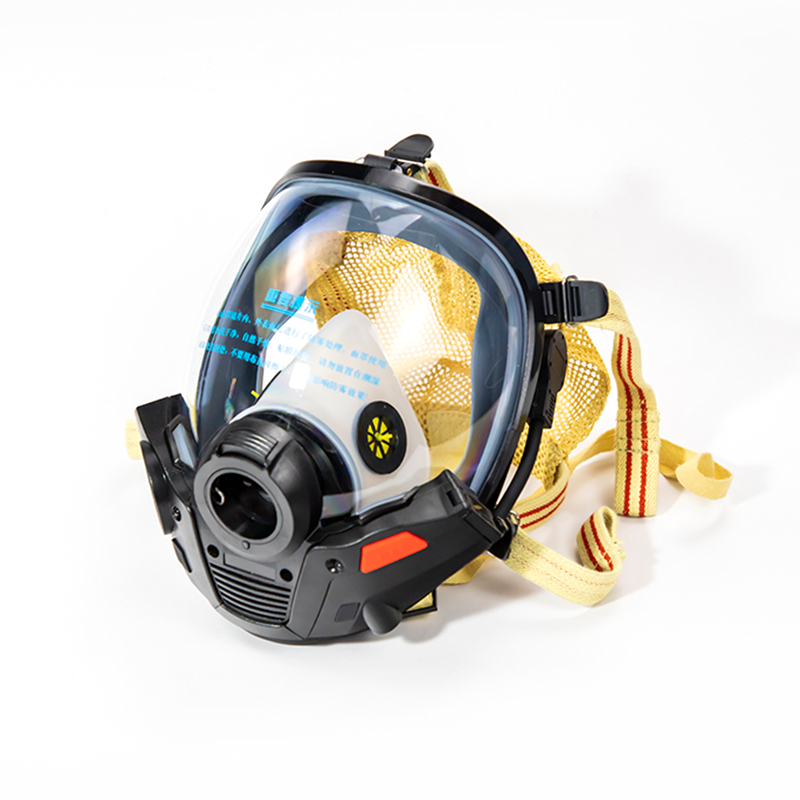
The KMQ-T positive-pressure firefighting air respirator communication mask and headset is a specialized piece of equipment that integrates respiratory protection and communication functions. Compared ...
See Details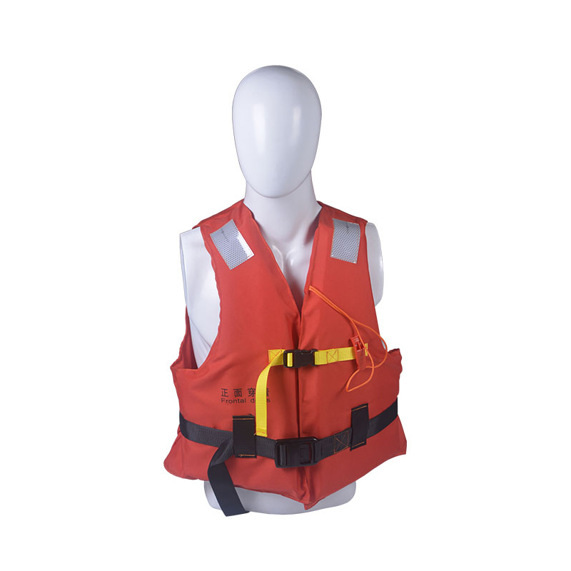
The product shown is a marine working life jacket, specifically designed for seamen and personnel during offshore or shipboard work activities
See Details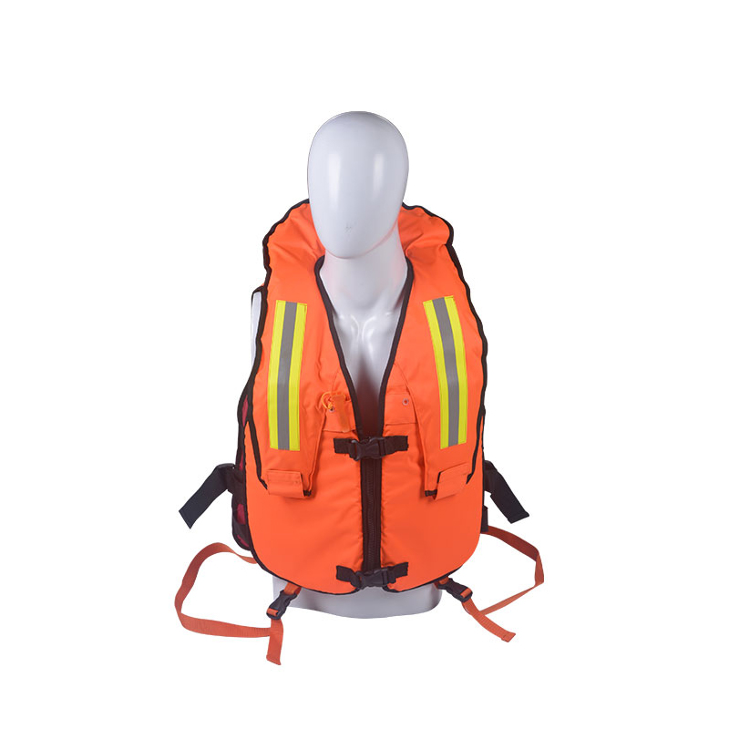
Designed for unexpected emergencies, this high-performance Auto-Inflatable Life Vest is your ultimate safety insurance. It stays ultra-portable and out of your way during normal tasks, but delivers in...
See Details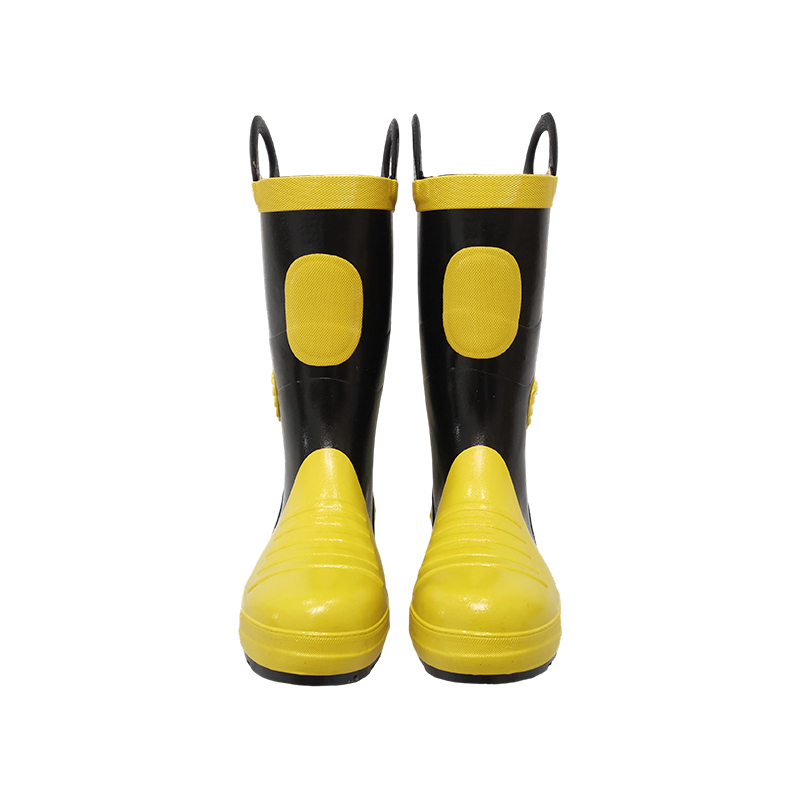
Description: The fire boots are made up of 2 parts, the shoe and the boot upper. Black colour with yellow lines. Multi-layers for the whole body. Smash-proof steel toes of the fire boots have inside &...
See Details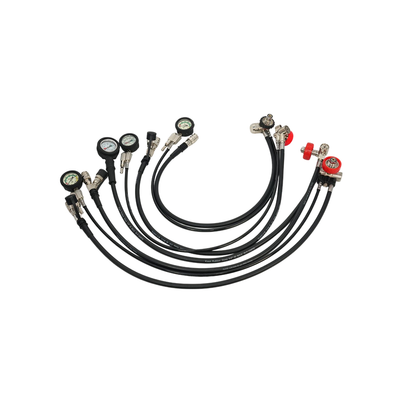
Introduction:The regulator assembly includes a pressure-reducing valve, medium- and high-pressure hoses, a mechanical pressure gauge, a remaining-air alarm, and a quick connector. It converts high-pre...
See Details
For any questions and feedback from customers, we will reply patiently and meticulously.


WhatsApp: 8618262215597
PHONE : +86-15370678666
EMAIL : zhouli@ntkaen.com
TEL: +86-513-88762099
Nantong Kaen Safety Equipment Co., Ltd. All Rights Reserved. ALL RESERVED. OEM Rescue Equipment Manufacturer Fire Protection Equipment Factory


 English
 Español
 中文简体
中文简体